
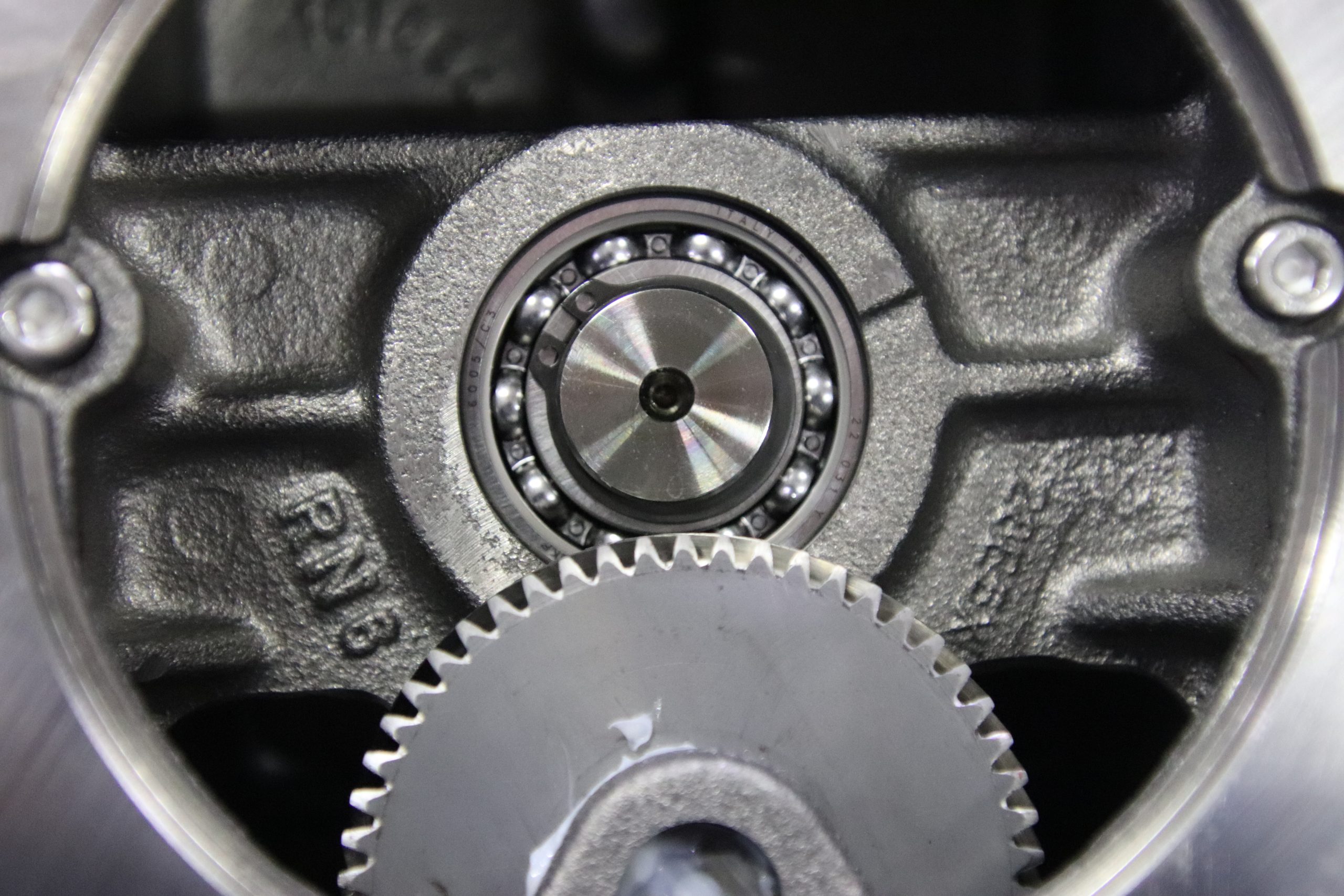
Machine builders, OEMs, and design engineers rely on gear reduction to match motor speed and torque to a machine’s work. In this guide, we break down what a gear reduction is, how the math works, and where STOBER reduction gears fit industrial designs.
Overview: Gear reduction concepts
Gear reduction uses meshing gears to lower the rotational speed and increase the load torque. Since mechanical power equals torque multiplied by rotational speed, an ideal reducer should trade speed for torque.
The main benefit is torque multiplication. Reduction gears allow a motor to run efficiently at higher RPM while delivering controlled, low-speed power. Gear reduction doesn’t increase horsepower; losses make the output power lower than the input power.
Gear train basics: Driving and driven gears
In a simple pairing, the input gear is the driving gear connected to the motor, and the larger output gear is the driven gear on the output shaft.
Input and output gears rotate in opposite directions; the input and output shafts remain parallel in a spur or helical pair, while other forms redirect power between intersecting or skew axes.
In the example below, a 20-tooth driving gear turns an 80-tooth output gear. The driving gear completes four turns per output turn, creating 4:1 reduction. The output gear turns slower and delivers greater torque, minus losses.
Simple 4:1 gear train
- Driving gear: 20 teeth
- Driven output gear: 80 teeth
- Four input turns equal one output turn
- Gear ratio: 80 ÷ 20 = 4:1
Gear ratios and gear ratio calculations
You can determine gear ratios by dividing the driven-gear teeth by the driving-gear teeth: ratio = output teeth ÷ input teeth.
With a matching module or diametral pitch, ratio = output pitch diameter ÷ input pitch diameter. A 15-tooth driving gear and 75-tooth driven gear produce 75 ÷ 15 = 5:1. Output runs at one-fifth of the input speed.
Higher gear ratios decrease speed and raise ideal torque by the same factor. This means that a 2:1 set halves speed and doubles torque; 4:1 cuts speed to one-quarter. Multiply stage ratios: 3:1 followed by 4:1 gives 12:1.
Common gear types in gear reduction systems
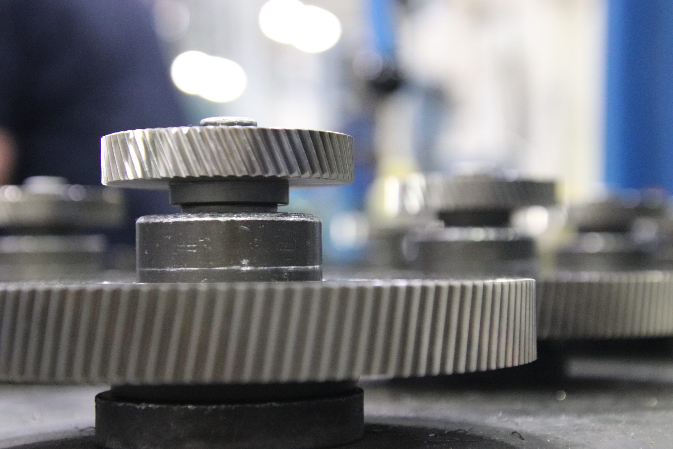
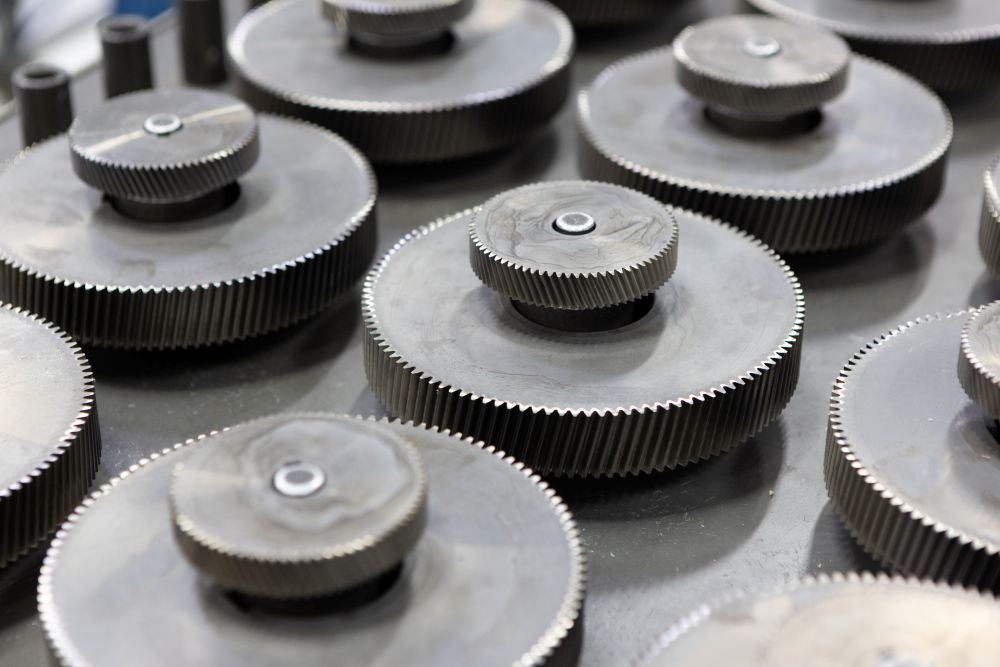
Helical gears have angled teeth that engage gradually, which supports smooth meshing and quiet, efficient operation. They also create axial thrust that bearings must carry. Helical gears are good for conveyors, packaging and printing equipment, and automation axes that need reliable, low-noise reduction gears.
Bevel gears transmit power between intersecting shafts, usually at 90 degrees. Bevel or helical-bevel reduction gears are ideal for right-angle mixers and conveyors, since their intersecting-shaft layout redirects power 90 degrees between motor and output axes. Pick parallel-shaft gearboxes for narrow footprints, belt or chain connections, or high radial loads.
Planetary gears place planets around a sun gear. Load sharing grants planetary gears high torque density, stiffness, and compact gear ratios for robotics. Worm reduction gears often deliver 10:1 to 60:1 in one stage, but with lower efficiency. Strain-wave designs are suitable for compact, high-ratio precision motion when load, life, and compliance requirements allow.
Gear material and surface treatments
Industrial driving gear and output gear sets use alloy or carbon steel for strength and fatigue resistance. Case-hardened steel combines a wear-resistant surface with a tough core to handle heavy loads. Stainless gear material is ideal for food processing, washdown, corrosive areas, and clean equipment when hygiene outweighs cost.
Carburizing, nitriding, superfinishing, and coatings can also enhance fatigue performance. Always validate treatments against the load, lubricant, temperature, material, and required life.
Design considerations for gear reduction systems
First, determine the required output torque, motion profile, motor speed, duty cycle, and service factor. Add a safety margin for shocks, starts, and reversals. To prevent unplanned downtime, select gear ratios that place the motor in an efficient range.
For precision systems, specify the backlash, repeatability, torsional stiffness, and lost motion. Check the radial, axial, and moment loads at the output shaft, and confirm mounting flatness, alignment, coupling fit, and housing rigidity. Poor alignment raises friction, noise, and wear, which gear reduction alone cannot correct.
Efficiency, losses, and lubrication
Mesh friction, bearing and seal drag, lubricant churning, misalignment, and heat can all limit efficiency. Helical reduction gears are often more efficient than worm sets, but ratio, load, and speed shape the actual performance.
Choose lubricant viscosity and chemistry for the gear type, load, speed, temperature, regulations, and duty cycle. Follow manufacturer instructions on fill quantity, intervals, and approved products.
Applications: Automotive, robotics, and industrial machinery
Automotive transmissions use reduction gears to control wheel speed and torque; differentials split the torque while the wheels turn at different speeds. Higher gear ratios provide torque for starting and climbing. In robotics, meanwhile, planetary gears and low-backlash reduction gears help joints lift loads and repeat precise motion.
Industrial gear reduction can drive conveyors, indexing tables, mixers, fillers, and packaging lines. Across these settings, gear reduction allows motors to efficiently deliver the necessary force and pace.
Selecting gearboxes and geared motors for OEMs
STOBER provides precision gearboxes, motors, and geared motor solutions. Our inline servo gearboxes offer helical and planetary options with five-year warranties. Assembled in Maysville, Kentucky, our gearboxes can ship in one day.
You can use the STOBER Configurator to compare different products, gear ratios, torque, and motors. Our engineers are here to help assess loads, precision, mounting, and environment.
Maintenance best practices
Be sure to stick to the manufacturer’s lubrication schedule. Oil life comes down to lubricant, temperature, contamination, speed, load, and duty cycle; some STOBER reduction gears are maintenance-free. Inspect all seals for leaks or ingress, check the breathers, and correct alignment before teeth and bearings are damaged.
Record the baseline temperature, vibration, and sound, then check for trends at regular intervals. Vibration and temperature can indicate misalignment, looseness, lubrication trouble, and gear or bearing faults.
Quick calculations and examples
For 4:1 reduction, select a 20-tooth driving gear and 80-tooth output gear. Ratio = 80 ÷ 20 = 4. At 1,800 RPM input speed, output speed = 1,800 ÷ 4 = 450 RPM. And with 10 N·m input torque, ideal output torque = 10 × 4 = 40 N·m.
For two stages, pair a 20-tooth driving gear with 60 teeth for 3:1, then pair a 15-tooth driving gear with 60 teeth for 4:1. Total = 3 × 4 = 12:1. With matching tooth sizes, pitch diameters also work: 100 mm driven diameter ÷ 25 mm driving diameter = 4:1.
Specification checklist and resources
Before you request a quote, document your load and peak torque, motor data, target speed, ratio, duty cycle, backlash, stiffness, shaft loads, mounting, envelope, lubricant, temperature, and washdown needs. This helps the applications engineering team narrow the reduction gears and identify tradeoffs.
Explore STOBER products or contact us for engineering support.

 Introducing the cLEAN Integral Unit: A compact washdown drive solution for OEMs
  One tool, more possibilities: Discover complete STOBER solutions with new Matching Products feature
  What are the main components of a gearbox?
  How long does a gearbox last? Lifespan, warning signs, and maintenance