
From compact actuators to large-scale gearboxes, gears form the backbone of reliable power transmission systems. Engineers and designers often evaluate tradeoffs between different types of mechanical gears when determining how torque should move through a system, such as spur gears vs. bevel gears or helical gears vs. spur gears.
Questions around layout, reduction requirements, efficiency, and durability quickly shape this decision. In many cases, the choice involves considering mechanical constraints that define what is possible rather than deciding based on preference.
The following gear selection guide helps you understand the core differences between spur, helical, bevel, and worm gears, so you can match the gear type to the application with confidence and clarity.
Spur, helical, bevel, and worm gears explained
These are among the most common types of gears used in mechanical power transmission systems. At a basic level, each gear style differs in tooth shape and shaft arrangement:
- Spur gears use teeth cut straight across the gear face and transfer torque between shafts that run side by side.
- Helical gears incorporate teeth cut at an angle, allowing motion to transfer between parallel shafts with a more progressive engagement pattern.
- Bevel gears are formed on a tapered, cone-shaped surface, enabling torque to transfer between shafts that meet at a common point.
- Worm gears consist of a threaded shaft that drives a mating wheel, typically changing motion direction while delivering significant speed reduction.
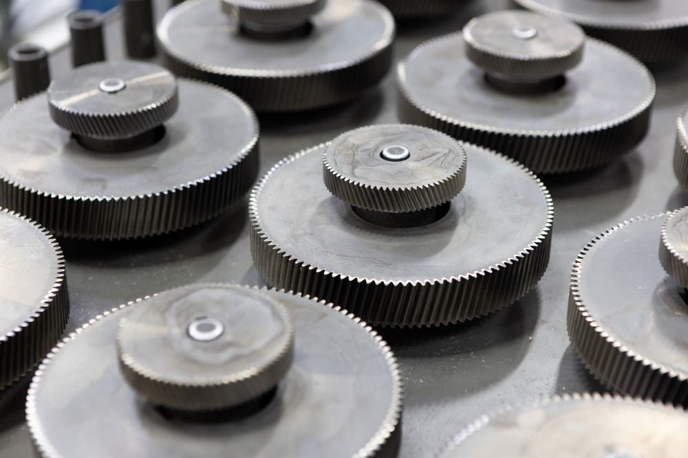
Spur gear
This type of gear has a straight tooth profile cut parallel to the gear axis and moves torque between two parallel shafts through direct tooth engagement.
Since the teeth engage suddenly along their full width, the gear transfers force efficiently and predictably. The simplicity of this straight tooth geometry makes spur gears foundational in many gearbox gear types.
At a conceptual level, torque transfer happens through rolling contact between teeth along parallel axes.
Helical gear
A helical gear uses angled teeth wrapped around the gear body in a helix pattern. The angled profile causes teeth to engage gradually rather than all at once. The gear transmits power between parallel shafts, but engagement happens progressively across the tooth face.
This gradual engagement influences smoothness and load sharing. But the angled geometry also introduces axial thrust along the gear axis.
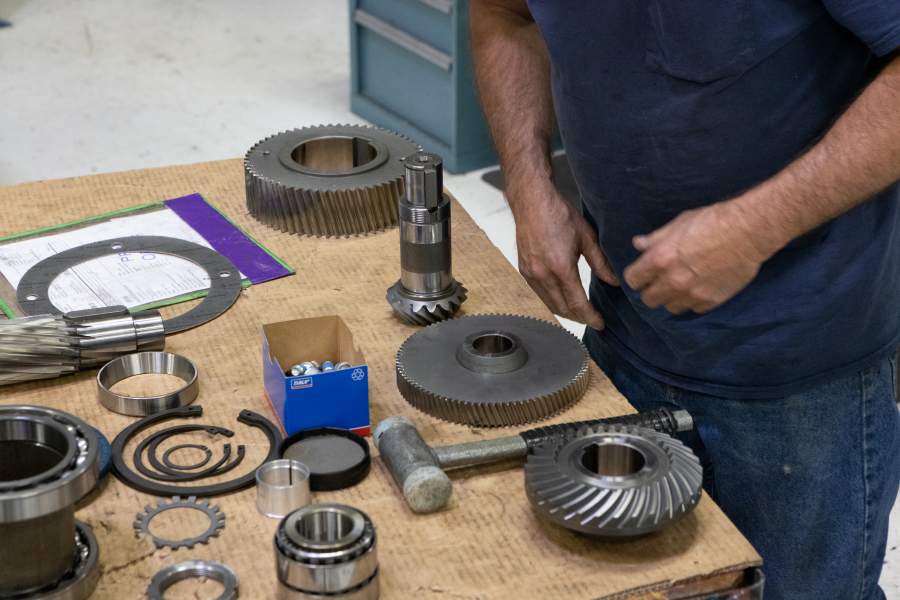
Bevel gear
A bevel gear has conical geometry, with teeth that are cut along a tapered surface, allowing motion to transfer between shafts that meet at a common point. This is the defining feature of bevel gear systems: they transmit motion between intersecting shafts, often at 90 degrees.
Rather than rolling along parallel faces, bevel teeth engage along angled paths on conical surfaces, redirecting torque.
Worm gear
A worm gear consists of a threaded worm (a screw-like shaft) that meshes with a gear wheel and typically drives it at a right angle. Rather than primarily rolling contact, the motion relies more heavily on sliding interaction between surfaces.
This geometry enables compact right-angle layouts and large reduction ratios in a single stage.
Note that there’s no best gear overall. Instead, the differences become meaningful when comparing layout constraints and reduction needs, along with operating conditions.
Spur gear vs. bevel gear: Shaft direction matters
The primary difference between a spur gear and a bevel gear comes down to shaft orientation. Spur gears are designed for systems where the input and output shafts remain aligned side by side, while bevel gears are used when the shafts meet at an angle and share a common intersection point.
If your layout requires a change in direction – such as transferring torque from a horizontal shaft to a vertical one – a bevel gear is typically necessary.
Parallel vs. intersecting shaft layouts
With spur gears:
- Shafts remain parallel
- Power flows in a straight line
- Layout is typically simpler
- Bearing loads are more predictable
With bevel gears:
- Shafts meet at a defined angle
- Torque direction changes
- The drivetrain can eliminate additional stages or couplings that would otherwise be required to redirect motion
In many systems, shaft layout is the first constraint that determines gear type. If the shafts need to intersect, a spur gear isn’t an option unless you redesign the architecture.
Bevel gear applications often work better in systems where space efficiency and directional change are both essential. The ability to change direction in a single stage reduces component count and mechanical complexity.
Spur vs. bevel gear performance tradeoffs
Once you establish shaft orientation, performance characteristics come into focus.
Tooth engagement and smoothness
Spur gears use direct tooth engagement across parallel axes. Since the entire tooth face engages at once, force transfer can be more abrupt.
Bevel gears engage along angled or conical tooth paths. Depending on whether the tooth form is straight or spiral, engagement may be more gradual.
These differences influence gear noise and vibration, especially at higher speeds. Engagement geometry and manufacturing precision, along with alignment, all play roles in perceived smoothness.
Load direction and bearing impact
Spur gears primarily generate radial loads.
Bevel gears introduce additional force components due to their angled engagement. These forces can influence key factors: bearing selection, housing stiffness, and support structure design.
This doesn’t make one better than the other; it simply means that the surrounding mechanical system needs to account for these load vectors.
Alignment sensitivity
Parallel-shaft spur systems tend to be more forgiving during installation.
Intersecting shaft bevel arrangements typically require more precise setup to ensure correct contact patterns. Otherwise, misalignment can shift loads across the tooth face and affect durability.
Overall, when evaluating spur gear vs bevel gear performance, the real differences often stem from system-level factors rather than tooth shape alone.
Worm gear vs. spur gear: Reduction and backdriving
Comparing these types of mechanical gears often centers on reduction capability and backdriving behavior.
Reduction in a compact layout
Spur gears generally provide moderate reduction per stage, so achieving high ratios often requires multiple stages.
A worm gear can deliver large reductions in a single stage, especially in right-angle layouts. This makes it attractive when space is limited and high reduction ratios are required.
Contact mechanics and efficiency
Spur gears rely primarily on rolling contact.
Worm gear systems transfer motion mainly through sliding interaction between the worm and the wheel. This sliding interaction increases friction, potentially influencing heat generation and overall efficiency.
In a gear efficiency comparison, this distinction is important. Sliding systems may require additional attention for lubrication and thermal management.
Backdriving behavior
Spur gears are typically backdrivable: If torque is applied at the output, it can drive the input shaft.
Worm systems are often selected for resistance to backdriving, but this characteristic depends on lead angle and friction conditions, along with application details. It should never be assumed without validation.
When evaluating bevel gear vs. worm gear solutions for right-angle layouts, consider the primary driver: reduction, efficiency, or backdrive resistance.
Where helical gears fit in
A helical gear occupies an interesting position in gear design considerations. It operates between parallel shafts like a spur gear, but its angled tooth profile changes engagement behavior.
Helical gear vs. spur gear
The main difference between these types is tooth geometry.
Helical gears:
- Engage gradually
- Share load across multiple teeth
- Can reduce vibration in certain conditions
Spur gears:
- Use straight tooth engagement
- Transfer load more directly
- Avoid axial thrust
The angled teeth of a helical gear introduce axial thrust along the shaft. Bearings need to absorb that thrust; it needs to be counteracted through design.
Helical tooth forms in bevel systems
Helical geometry also appears in bevel systems as spiral bevel designs.
Rather than straight tooth bevel geometry, spiral bevel teeth engage progressively (similar to parallel-shaft helical gears). This can influence smoothness and load distribution in intersecting shaft systems.
Helical gears aren’t a universal replacement; they’re an alternative within both parallel and intersecting shaft layouts.
Choosing the right gear type
Choosing the right gear type starts with constraints, rather than preferences. Early decisions shape system reliability and maintenance requirements, along with long-term efficiency.
Here’s a practical framework:
- Shaft orientation: Parallel or intersecting shaft? Is a direction change required?
- Reduction range: Moderate reduction or high ratio in a single stage?
- Space constraints: Is axial length limited? Is right-angle packaging necessary?
- Efficiency and thermal sensitivity: How critical are heat management and energy loss?
- Load direction and duty cycle: Continuous duty? Shock loading? Reversing motion?
- Operating environment: Temperature, lubrication, contamination exposure
These factors narrow your gear options quickly.
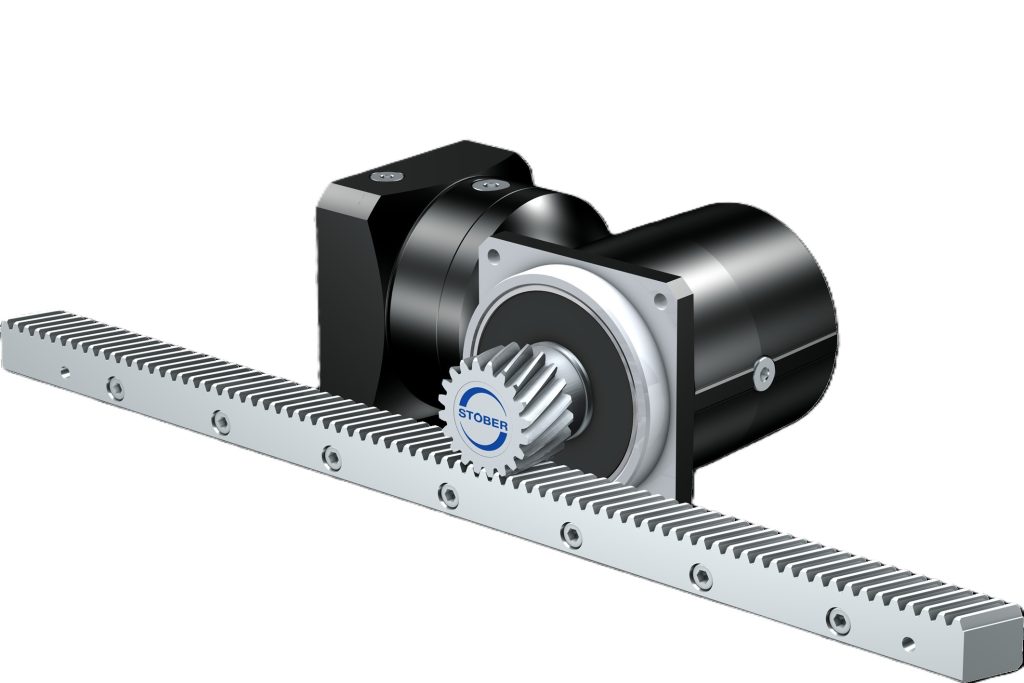
For example, many spur gear applications appear in systems where simplicity and efficiency, along with parallel shafts, dominate. Worm gear systems emerge when you need compact right-angle reduction. Bevel gear applications become necessary when torque direction must change cleanly.
Understanding how gears transmit power – and how gear engagement types influence system behavior – is important. But deeper decisions often depend on the science of gear tooth design and how those teeth behave under real load conditions.
When evaluating industrial gearbox types or broader industrial gear applications, application engineering support becomes valuable, especially when tradeoffs compete.
STOBER products are engineered to address real-world constraints across a wide range of gearbox gear types. Using the STOBER Configurator, engineers can size and configure solutions based on torque, speed, mounting requirements, and other parameters rather than assumptions.
Choosing the right gear type goes beyond simple geometry. It involves integrating mechanical layout, load behavior, efficiency targets, and long-term durability into one cohesive system.
Explore STOBER products for applications across many industries, and contact STOBER to discuss solutions that improve reliability, efficiency, and long-term performance.

 STOBER introduces next-generation KS servo gearbox with compact design
 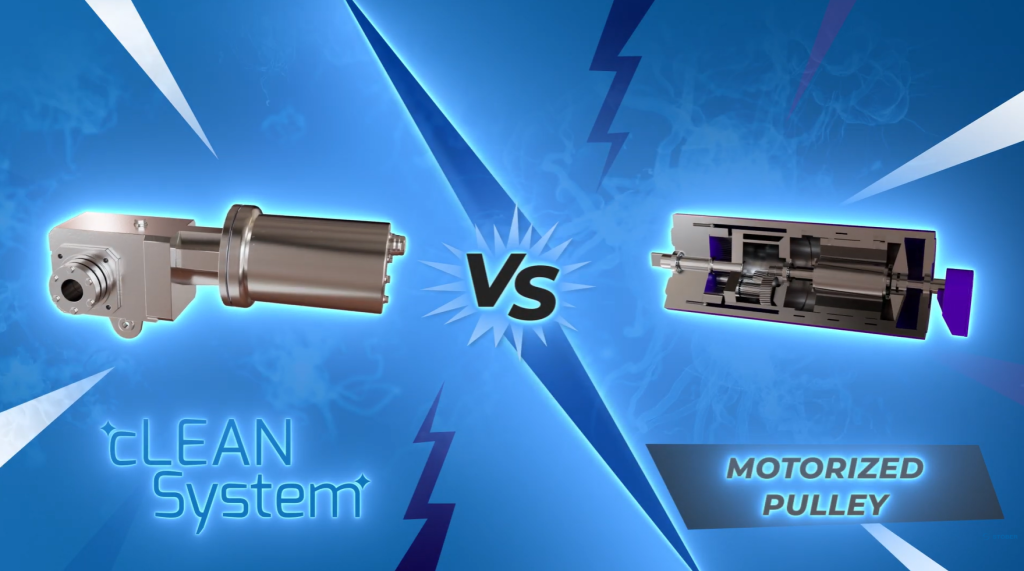 STOBER cLEAN System outperforms motorized pulley in food processing environments
  Ideal gearbox selection: Practical sizing checklist to save money