
Robotic systems operate based on how well their joints are designed. A carefully engineered arm structure isn’t enough if the joints aren’t performing. Motion starts and stops, then gets refined right at the joint level, so even small imperfections tend to show up as bigger issues.
Robotic arm joint design sits right at the intersection of mechanics, electronics, and control systems. It defines how each joint moves, how much load it can handle, how precisely it can position itself, and how consistently it can repeat that motion over time.
In real automation environments, it needs to move the same way every single cycle, even under changing loads or temperature shifts.
A solid approach to robotic arm joint design principles looks at torque, stiffness, thermal behavior, and feedback as one connected system. Each joint adds a degree of freedom, and those stack quickly. So even minor errors don’t stay that way for long. Instead, they build up across the arm’s kinematic chain. That’s why robot joints are performance-critical elements, not just mechanical pivots.
Robot joint design engineering determines whether a robot can handle real-world tasks such as fast pick-and-place operations, precision assembly, and heavy lifting without losing accuracy, stability, or reliability over time.
Core components that shape robotic arm joint design
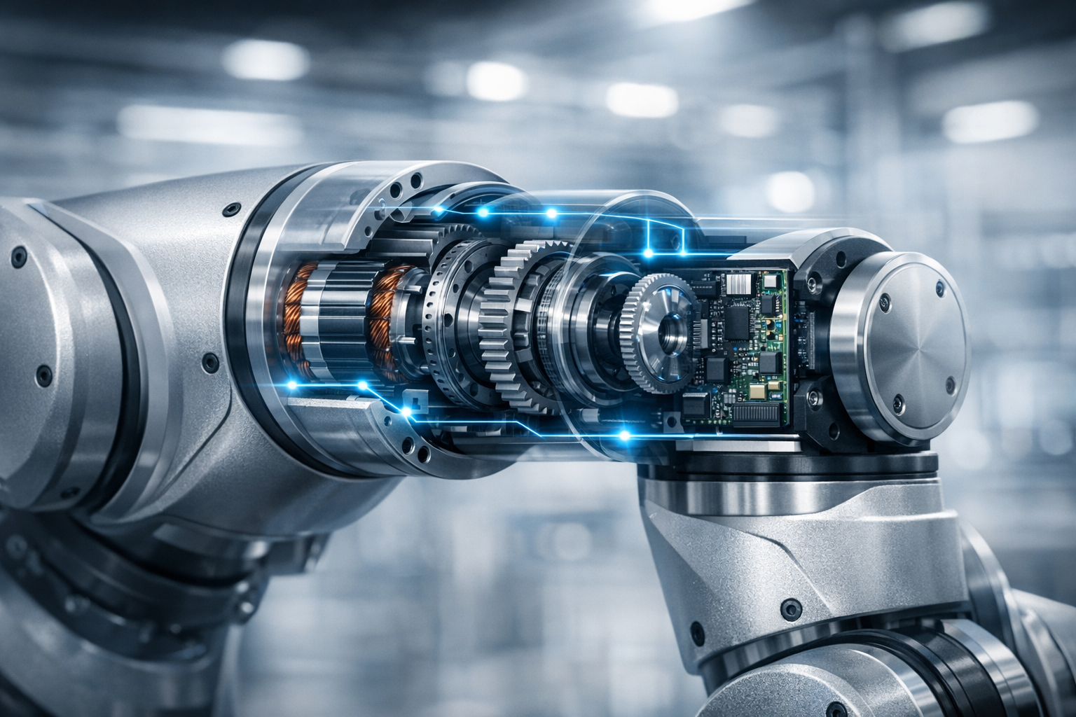
Every joint in an industrial robot joint design setup is a small system on its own. It’s a mix of mechanical and electrical components all trying to stay perfectly in sync under load, not just one part doing the work.
Here’s what usually goes into it:
- Motor (servo motor or stepper motor for robotic joints): This is where motion starts. It sets speed, torque, along with response behavior.
- Gearbox (robotic joint gearbox): Think of this as the translator; it turns fast motor speed into usable torque and controlled movement.
- Encoder: This is the feedback loop’s “eyes,” constantly tracking position and speed.
- Bearings: These keep everything moving smoothly while handling both radial and axial loads.
- Structural housing: This is the backbone that keeps everything aligned and stiff under stress.
- Shafting and couplings: These move torque through the system without wasting energy.
- Control electronics: This is the coordination layer that keeps all joints working together in sync.
In articulated robot joint design, none of these parts really work in isolation. You can have a great motor, but if the gearbox has too much backlash or the housing flexes under load, performance drops fast. And precision mechanics can’t save a weak control loop.
That’s why robot joint actuator design is treated as a full system problem. Engineers are constantly balancing torque transfer, heat buildup, stiffness, and feedback accuracy. Even small issues like bearing deflection or thermal expansion can quietly reduce robotic joint load capacity and long-term precision.
The biggest design challenges in robotic joints
If there’s one thing about joint design challenges, it’s that everything is a tradeoff. You improve one part, and something else usually gets harder.
Take size, for example. Compact robotic joint design is attractive because it can make robots faster, lighter, and easier to package. But shrinking them down makes it much harder to fit in everything you need without compromising performance: motor, gearbox, encoder, cooling, and wiring.
Weight is another issue, especially in a multi-axis robotic arm. Joints closer to the base end up carrying their own load and everything further out, so even small weight increases at the wrist can ripple backward and force redesigns in earlier joints.
Then there’s heat. High torque generates heat, so effective thermal management is necessary because rising temperatures can affect motors, lubrication, encoder stability, and long-term durability.
Other common challenges include:
- Fitting all robotic joint components into tight spaces without performance loss
- Keeping backlash in robotic joints low while still maintaining durability
- Balancing stiffness with weight so the arm doesn’t become overly heavy
- Holding accuracy during vibration, shock, and fast directional changes
- Managing high torque demands without sacrificing efficiency
- Designing joints that are serviceable in real industrial environments
- Reducing compliance that starts to show up at the end effector
One thing engineers may run into is deflection. Even when a joint feels rigid locally, small flex adds up across multiple links. Those tiny movements can become noticeable positioning errors, so stiffness at every stage matters, not just at the end. High joint stiffness also becomes even more important in applications where small positional errors can affect assembly quality or coordinated multi-axis motion.
How backlash grows over time
Backlash growth over time is rarely caused by a single failure. It is the result of gradual wear throughout the system.
Repeated reversing motion, high duty cycles, shock loads, and insufficient stiffness all contribute. If the gearbox is not designed to maintain tight tolerances under these conditions, lost motion increases. The change may be measured in arcminutes, but its impact on machine accuracy can be significant.
As backlash grows, the control system has to work harder to compensate. Positioning becomes less repeatable. Settling times increase. Surface finish and process quality begin to degrade.
How gearbox choice affects robotic arm joint design
Gearboxes end up influencing more than people expect. In many ways, they define how the whole joint behaves. They directly affect:
- Torque output
- Speed reduction
- System stiffness
- Backlash levels
- Packaging size and shape
Low-backlash performance is especially important. Small directional inconsistencies can stack up across multiple joints and throw off positioning at the tool center point. That’s why robotic joint gearbox selection has such a big impact on system accuracy.
But gearbox selection isn’t just about picking a ratio. Engineers also look at how stiff the system is under load, how it handles shocks, how efficient it stays over long duty cycles, and how well it integrates with the motor system.
Pairing a gearbox with a servo motor for robotic joints involves matching system behavior, not just specifications. If factors such as the torque curve, inertia, and control loop tuning do not align properly, the system can feel unstable even if every component is technically high quality.
Different gearbox styles also bring different strengths. Planetary systems are often chosen for durability and efficiency, while harmonic-style designs tend to show up when compact size and very fine positioning matter more.
In practice, engineers lean on references (for example, a gearboxes for robotic automation selection guide) or compare inline planetary gearboxes for robotics to make sure the choice fits real motion behavior, not just catalog numbers.
Designing for accuracy, load, and motion control in robotic arms
Accuracy in robotics results from proper alignment between structure, sensing, control, and other system factors. This relationship explains an important principle: the farther the load is from the joint, the more torque the joint must handle.
In robotic arms, distance changes constantly. That changing leverage is one reason robotic joint torque requirements can vary dramatically across different arm positions and motion profiles.
Accuracy depends on a combination of elements working together, such as encoder resolution, gearbox stiffness, bearing alignment, and motion control tuning. Maintaining consistent joint precision requires mechanical and control elements to remain aligned, even during rapid acceleration and continuous operation.
In real use, models never match reality perfectly. Loads change, temperatures drift, and parts wear down. That’s why modern systems rely heavily on adaptive control strategies. Engineers tune motion systems so they can stay stable even when conditions shift.
Thermal drift is another subtle issue. As components heat up, small dimensional changes can affect alignment and feedback accuracy. Over time, this can show up as drift in positioning unless the system is designed to compensate for it.
Resonance is another factor that is often underestimated. Every robotic arm has natural frequencies, and if motion commands hit those frequencies at the wrong time, vibrations can build instead of disappear. That is where stiffness, damping, and control tuning all need to work together.
Key system-level considerations include:
- Payload changes across the workspace
- Acceleration and deceleration behavior
- Shock loads during direction changes
- Multi-axis coordination timing
- Real-time disturbance correction
All of this determines whether the robot feels stable and precise or slightly off, even if individual specs look fine.
What good robotic arm joint design looks like in modern automation
Modern robotic systems are moving away from thinking in isolated parts. Instead, robotic arm joint design is increasingly focused on integrated systems that behave predictably under real-world conditions.
That means motors, gearboxes, encoders, and controllers are no longer selected independently; they are designed to work together from the beginning. It reduces mismatch and makes performance more consistent across operating conditions.
Good design usually comes down to a few priorities:
- Consistent torque delivery, even when load changes
- Low-backlash motion that stays repeatable over time
- Efficient heat handling during long duty cycles
- High stiffness without making the system overly heavy
- Compact layouts that still hold up mechanically
But none of that matters without starting from the application. Payload, reach, duty cycle, and environment shape every decision. So a system built for high-speed sorting looks very different from one built for heavy industrial lifting.
Long-term reliability is just as important as peak performance. These systems are expected to run for millions of cycles, so wear behavior and service life matter just as much as initial specs.
When requirements get tight, especially around precision and compact design or low backlash, it’s common to bring in motion expertise early. Tools like the STOBER Configurator help engineers compare integrated drive solutions and narrow down gearbox and actuator options before committing to hardware.
Overall, robotic joint design involves more than simply making motion possible. It revolves around making it reliable, repeatable, and stable enough that the rest of the system can depend on it — cycle after cycle, shift after shift.

 Eight warning signs that you need industrial gearbox repair
  STOBER recognized as Maysville Area Chamber’s Large Business of the Year
  Can you repair a gearbox? Signs, costs, and next steps
  Introducing the cLEAN Integral Unit: A compact washdown drive solution for OEMs